Why does a garden need a robot
It doesn't, technically. That's kind of the point. Garex is my excuse to combine every hobby I have into one machine: 3D printing, electronics, LLMs, and RC-car parts I have been hoarding for years. The premise is simple even if the build is not: a small, cat sized rover that lives outside, looks around, remembers what it sees, and writes about its day like a tiny cynical robot diary keeper.
Wall-E was the original look I was going for. Boxy torso, expressive eyes, treads or wheels underneath. That aesthetic stuck around in spirit, but the actual shape of the thing changed a lot along the way, more on that later because it is honestly one of the more fun dead ends in this whole project.
The parts bin era
Before there was a frame or even a real plan, there was a drawer. Years of "I'll use this for something someday" finally got a something. A dead dashcam got cracked open for its little gimbal motor and camera board, thinking maybe that becomes an eye. A broken RC toy gave up its motors and gears. Old Lego Technic parts (yes, actual Lego, don't judge) got pulled out because a geared motor is a geared motor no matter who made the plastic around it.
None of this ended up being exactly what shipped in the final build, most of it got replaced by purpose bought motors later, but it is what got the project moving in the first place. Sometimes you don't need the right part, you need any part, just to prove the idea works before you spend real money on it.
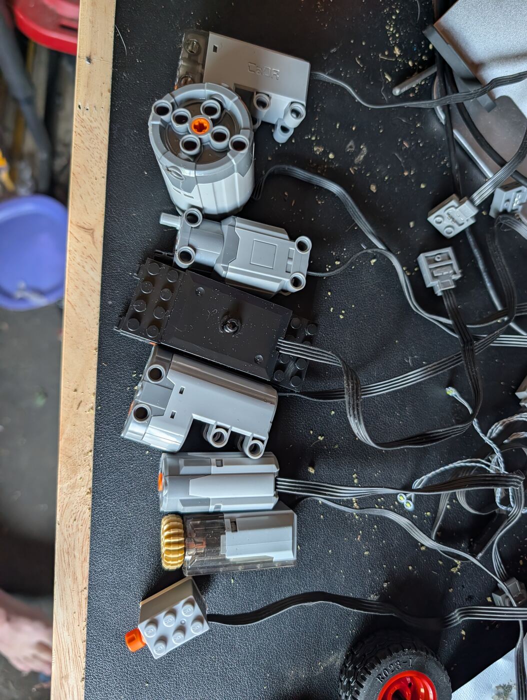
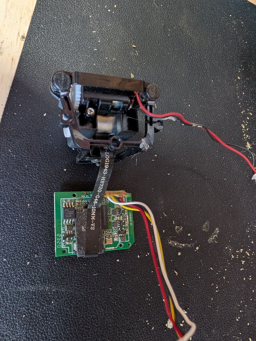
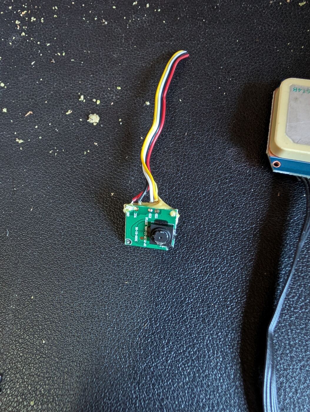
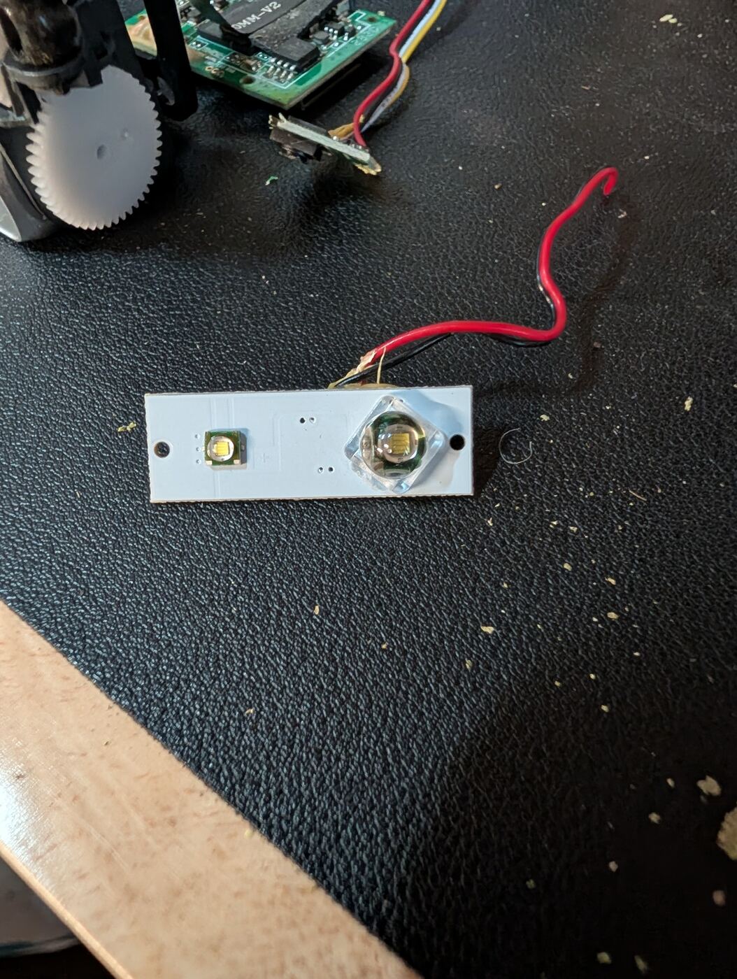
Top-down shot of a cluttered workbench drawer full of salvaged robot parts (motors, gears, wires, small circuit boards), a hand slowly sorting through them, warm workshop lighting, shallow depth of field, documentary style
The frame
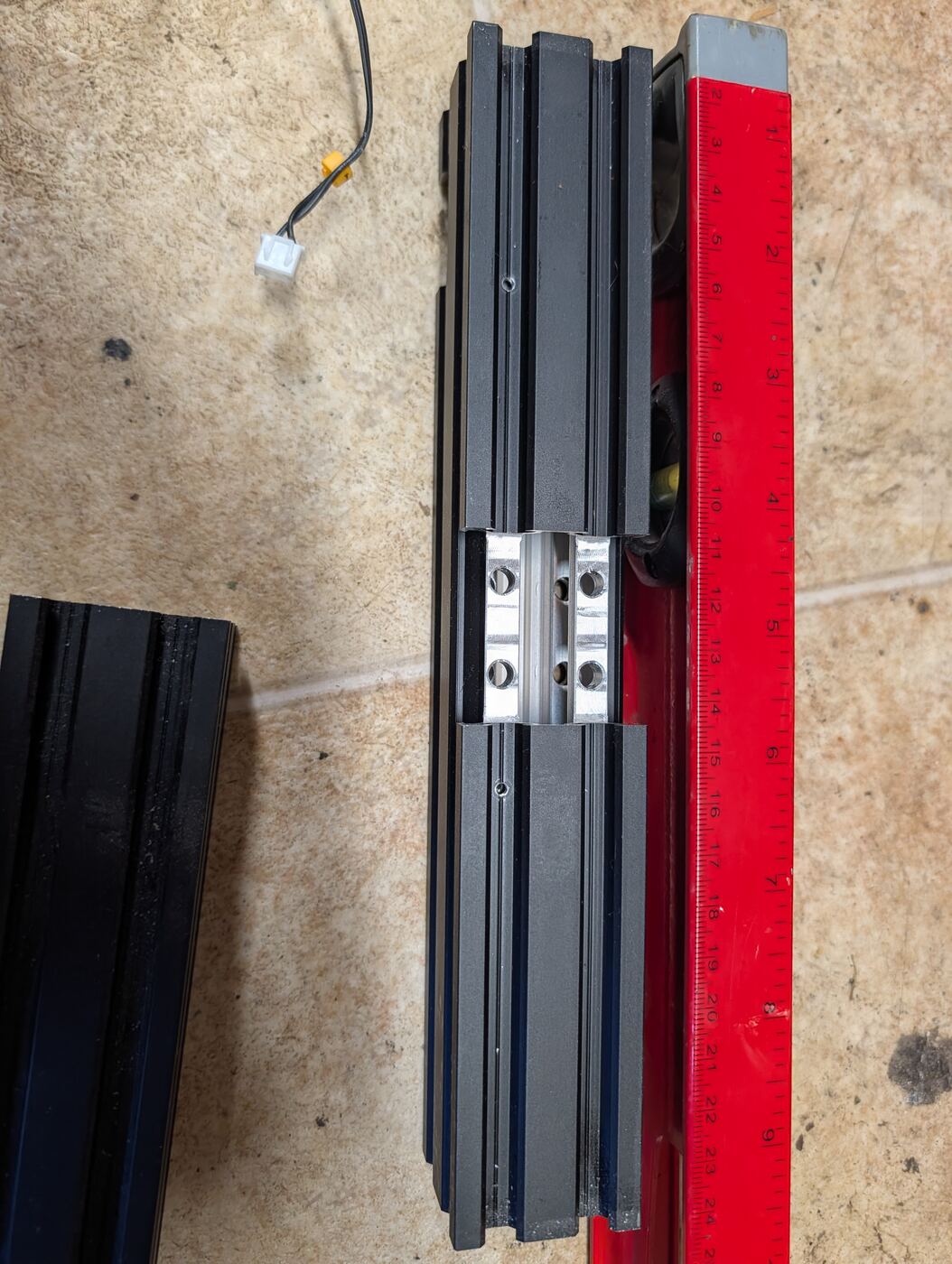
Garex's skeleton is 2040 V-slot aluminum extrusion, the same stuff 3D printers are made of, cut and bolted into a rectangle. Nothing fancy here, just measure twice, cut once, and discover that "once" sometimes needs a second try anyway. The frame ended up 480mm long outer, about 210mm wide, with cross rails set 40mm in from each end so the wheels have some bumper protection sticking out past them.
The suspension rabbit hole
This is the part of the build that ate the most weekends. My first plan was a rigid chassis, motors bolted straight to the frame, wheels bolted straight to the motors, done. Simple. Then I actually thought about where this thing lives (a yard, dirt, roots, rain) and decided the motors needed to stay up and dry, which means the wheels need to move independently underneath them. Which means suspension. Which means I basically had to relearn how an RC crawler's suspension geometry works, from scratch, at 11pm, more than once.
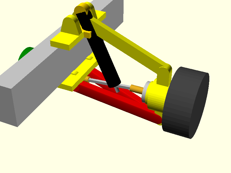
Each wheel corner ended up as its own little assembly: an RC-style trapezoid lower arm hinging off a 3mm steel rod, a 3D printed hub carrier pressed onto bearings, an upper link running parallel to the lower arm to keep the wheel standing upright through its travel, and an actual RC shock absorber soaking up the bumps. The driveline itself uses two universal joints per wheel so the motor can sit fixed on the frame while the wheel bounces up and down independently, basically a tiny version of what a real 4x4's front axle does.
The dead end that taught me the most: I originally drilled straight into the motor's output shaft and assumed the geometry would just work itself out. It did not. The joint-to-joint distance through suspension travel has to stay constant or the whole thing binds up, so the inboard U-joint has to sit exactly on the arm's hinge axis. Once I understood that, everything else about the driveline clicked into place. Before that, it was just me starting at a CAD screen going "why does this look wrong."
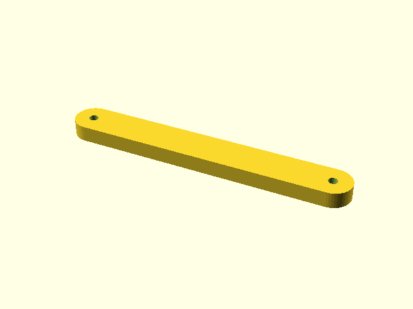
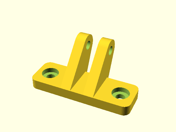
Close-up macro shot of a small robot suspension assembly flexing up and down, RC-style shock absorber compressing and extending, U-joint driveline visibly rotating and pivoting, clean studio lighting, slow motion feel, mechanical and precise
Printing everything
Almost every custom part on Garex is 3D printed. Hub carriers, hinge posts, axle sleeves, the shock mounts, all of it comes off one of two printers: a Mega X for the bigger structural bits, and a Bambu A1 Mini for small precise parts and wheels. PETG for anything that needs to take a bump, TPU when something needs to flex or grip.
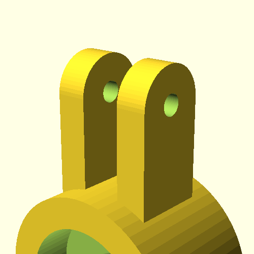
The print queue at the time of writing: six hub carriers (version two, the first version's mounting tabs were too thin and just snapped), six hinge posts in two variants, a little drill jig I printed just to keep the U-joint holes lined up straight (drilling twelve of these by hand freehand would have gone badly), and six upper link brackets, pending one more measurement check before I commit to printing all six at once. Learned that lesson already, more than once.
Salvage keeps showing up here too. An old 3D printer mainboard (Aquila, RIP) got repurposed as the arm controller since it already has stepper drivers built in. Its metal enclosure panel, complete with a little cooling fan, is getting reused as a skid plate and vent for the electronics bay.

Time-lapse of a 3D printer nozzle laying down layers of a small yellow mechanical part (a hub carrier bracket), print bed visible, gradual build-up from raft to finished part, workshop background slightly out of focus
The shape pivot (still in progress)
For a while Garex was designed as a tall Wall-E style torso sitting on top of the suspension. Then I actually did the math on how tall the brain compartment and motors needed to stack, and realized the whole thing was heading toward almost a meter tall on rough garden terrain. Too top-heavy, too tippy, and honestly too big for what was supposed to be a cat-sized robot.
So the whole upper body got rethought as a low, flat armored hull instead, more like a small military rover than a Pixar character. A rotating turret on top carries a single arm, and the eyes moved to a fixed nose module at the front, styled a bit like a rally car's light bar. The persona stays the same (still a cynical, curious little machine), the silhouette just got a lot more grounded.
Honest status update: the Blender digital twin already reflects this new shape, but I'm still working through the Tinkercad version, which is the model I actually use to sanity check prints before committing plastic to them. That part is not done yet, it's an active work in progress, not a finished reveal.
Slow 360-degree turntable rotation of a low, flat, armored 6-wheeled rover with a rotating turret and single arm on top, matte olive drab and gunmetal color scheme, small glowing cyan eyes on the front nose, studio product-shot lighting on a plain background
What's next
- Finish drilling and printing the suspension print queue, get all six corners on the frame
- Bench test the motors and the Aquila arm controller before anything goes outside
- Finish the Tinkercad model of the new low-hull shape
- Print the nose module (eyes) and the turret ring gear
- Actually take it outside and see what "garden explorer" means in practice
A small low-profile 6-wheeled rover slowly driving across grass in a backyard garden, golden hour lighting, camera at ground level tracking alongside it, dust and grass blades visible, cinematic but grounded, not sci-fi